
Dry Pipe Sprinkler Presentation
Dry pipe sprinkler systems are usually installed in unheated buildings or where there is the possibility of sprinkler pipes freezing.
The dry pipe valve and related equipment must be in a heated location.
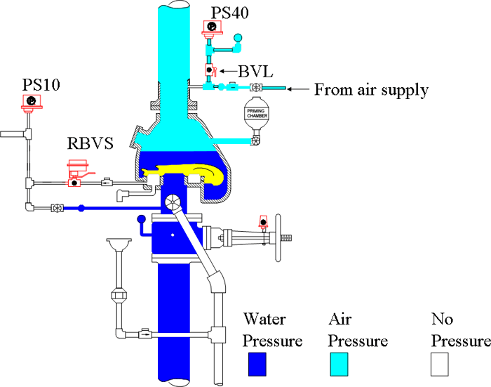
Dry systems have pressurized air in the sprinkler piping. This allows for supervision of the piping and keeps the dry pipe valve closed which prevents water from entering the system.
The system side of a dry pipe valve may be approximately 5 times larger than the supply side. This allows a lower pressure [usually 40 psi ], to hold back the city water supply. There may be a small amount of priming water on top of the valve to create a better seal.
Dry pipe valves have an intermediate chamber, or alarm port. This may run to the outside of a building to operate a water motor gong.
Under normal conditions, this section of piping has no pressure or water. The pressure type water flow switch is installed on this section of piping.
Vane type waterflow switches are not allowed on dry pipe sprinkler systems per NFPA13. Because when the dry pipe valve opens, the water rushes in with such force that the paddle could be ripped off of the flow switch.
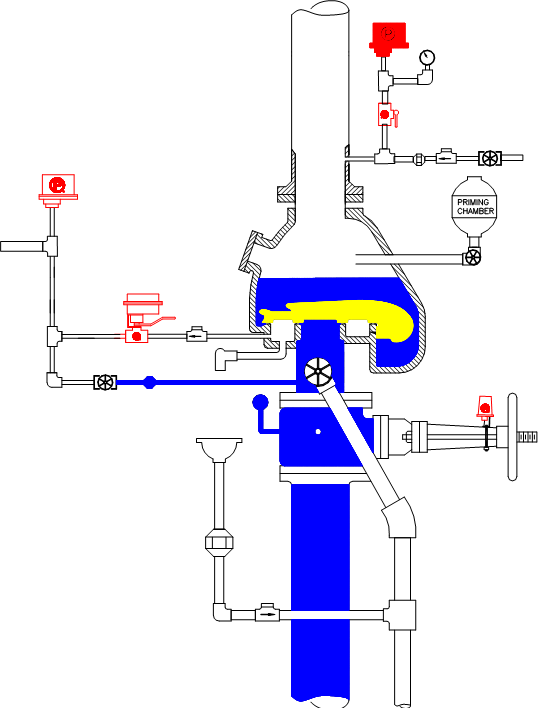
If a sprinkler opens, the air pressure will drop. When the pressure drops 10psi, the PS40 low air switch will trip sending a supervisory signal to the fire alarm panel. This is just an indication that there is low air pressure in the system, possibly caused by a compressor failure and someone needs to take action before the dry pipe valve trips.
The PS40 is factory set to trip at 30psi which should be 10psi below the normal air pressure in the system. And 10psi above the trip point of the dry pipe valve.
NFPA72 requires that the air pressure be monitored to detect a change of 10psi from normal pressure.
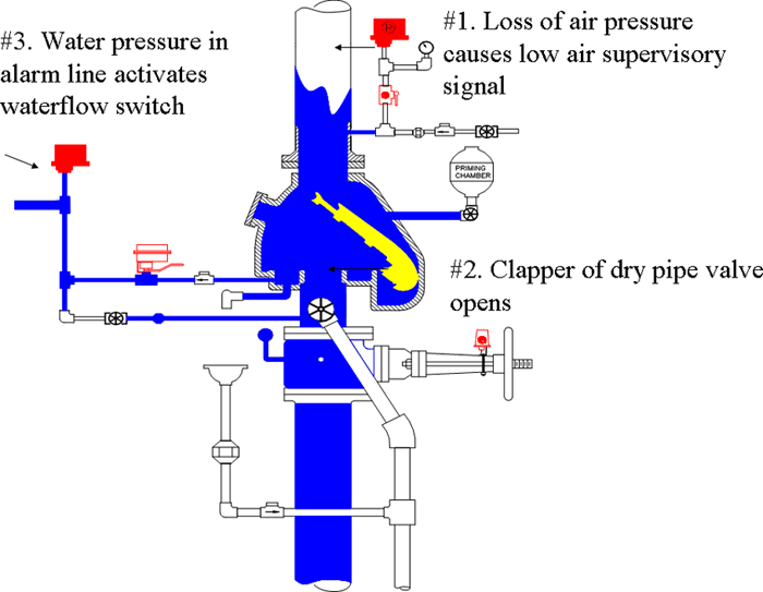
When the pressure drops low enough such as from an open sprinkler, the valve will open. This allows the water supply to fill the piping and be discharged through the open sprinkler.
When the valve opens, it also exposes the alarm line to the incoming water supply.
When the pressure in this line reaches 6psi, the water flow switch will trip.
Dry systems MUST use a pressure type flow switch. Per NFPA, vane type flow switches are NOT allowed.
There is no need for a retard on dry systems, in fact, retards are not allowed.
Testing
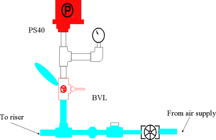
The low pressure switch can be easily tested with a Potter BVL bleeder valve. The BVL is a 1/2" ball valve with a small pinhole drilled in one end of the valve.
The valve is installed in line with the PS40 and a pressure gauge, when the valve is shut, it bleeds off the air from the BVL to the PS40.
This eliminates the person performing the tests from having to shut off the water supply, shut off the air compressor, open a union and bleed off air out of the entire system. And of course some day, someone will forget to shut off the water and accidentally bleed off too much air and trip the dry pipe valve which will make for a very bad day.
The gauge needs to be installed so that it can be determined at what pressure the PS40 trips at. Without the gauge, all you know is that the switch tripped, it may be at or below the pressure at which the dry pipe valve opens in which case the switch is not really doing anybody any good.
Testing
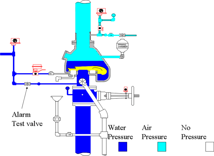
Testing of the waterflow switch on a dry pipe system is accomplished by opening the normally closed alarm test valve. This allows water to flow from below the dry pipe valve directly to the PS10.
If there is a shut-off valve between the dry pipe valve and the PS10, the valve must be supervised according to NFPA72 if the sprinkler system is required to be supervised. The Potter RBVS is a retrofit ball valve tamper switch made just for this purpose.
